
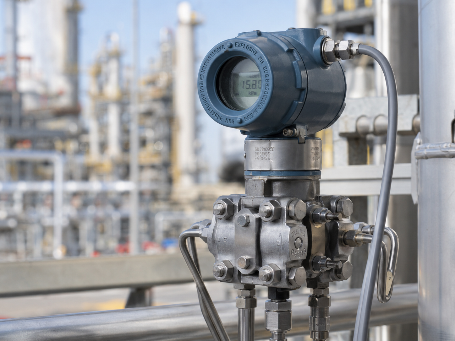
Pressure transmitter sizing is not simply choosing a device whose upper range is higher than the process pressure. A reliable selection starts with the measurement objective, then works outward through process limits, accuracy, materials, installation, and failure conditions.
1. Define what pressure you are measuring
Confirm whether the application needs gauge, absolute, differential, sealed-gauge, or multivariable measurement. The reference pressure changes the meaning of every value that follows. For differential-pressure applications, separately identify the maximum static line pressure and the differential span.
2. Establish the process envelope
Collect normal, minimum, maximum, start-up, shutdown, upset, vacuum, and test pressures. Include ambient and process temperatures, pulsation, vibration, and any cleaning or steam-out conditions. The transmitter must survive the worst credible condition even when that condition is outside the calibrated measurement range.
The lower range value (LRV) and upper range value (URV) define the calibrated span. Select a sensor range that comfortably contains the required LRV and URV without forcing the device to operate at an unnecessarily extreme turndown ratio.
3. Avoid the “bigger is safer” trap
An oversized range may survive the process but deliver poor resolution and larger percentage-of-span error at normal operating conditions. A good selection places the expected operating region in a useful portion of the calibrated span while preserving room for realistic transients.
4. Check accuracy as an installed system
Do not stop at the reference accuracy printed on a data sheet. Review total performance over temperature, static pressure effects for DP transmitters, long-term stability, remote-seal effects, impulse-line head, mounting position, and the accuracy of the receiving system. The dominant error may be installation-related rather than sensor-related.
5. Select wetted materials and process connections
Confirm compatibility for the diaphragm, process flange, O-rings, manifold, fill fluid, and impulse tubing. Corrosion, hydrogen permeation, plugging, freezing, and high temperature can all change the preferred construction. Verify flange rating and connection standards against the piping specification.
6. Decide how the instrument will be installed
- Direct mount or remote mount
- Two-, three-, or five-valve manifold
- Impulse lines, capillaries, or direct insertion
- Drain and vent orientation
- Heat tracing, insulation, and freeze protection
- Hazardous-area certification and enclosure rating
7. Complete the package, not just the model number
A strong datasheet records tag, service, range, units, output protocol, materials, process connection, manifold, mounting bracket, approvals, alarms, calibration, and documentation requirements. The loop drawing, P&ID, cable schedule, I/O schedule, and bill of materials should carry the same decisions.
Technical references
This article is general educational information. Apply project specifications, current manufacturer data, applicable codes, and qualified engineering judgement.