
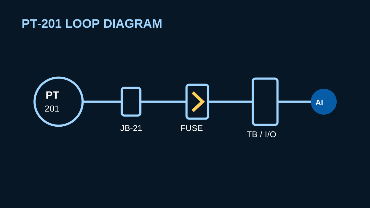
A loop diagram is the field-level map of an instrument signal. It should show the physical interconnections required to install, energize, test, troubleshoot, and maintain one loop. A good loop drawing removes ambiguity from every handoff between the device and the control system.
Show the complete signal path
Trace the loop from field instrument to local junction box, marshalling, barriers or isolators, power distribution, terminal blocks, I/O card, and final control destination. Identify cable numbers, pair numbers, wire colours or conductor numbers, terminals, shields, and grounding points.
Make power architecture explicit
State whether the device is loop-powered, separately powered, or supplied through an isolator. Show voltage, polarity, common returns, and any disconnecting means. Maintenance should not have to infer where power originates.
Why fusing matters
Properly designed fusing protects conductors and equipment, limits the effect of a fault, and provides a clear isolation point. The drawing should identify the fuse number, location, rating, and associated terminal. Fuse selection must match the circuit, power supply, conductor ampacity, inrush, hazardous-area design, and project protection philosophy.
Show shields and grounds correctly
Indicate where the cable shield is continuous, where it is insulated, and where it is bonded. A vague shield symbol can create multi-point grounding, noise, or unsafe assumptions during troubleshooting.
Include installation information
- Device tag and service
- Junction-box and terminal identifiers
- Cable, pair, and conductor identifiers
- Control-system cabinet, rack, slot, and channel
- Barrier, isolator, surge protection, or intrinsic-safety parameters
- Fuse, disconnect, and power-supply references
- Drawing and revision cross-references
Design for troubleshooting
The best loop diagram anticipates the technician’s questions: Where can I isolate this loop? Where should I measure current? Which fuse feeds it? Which terminals should be lifted? Where is the shield grounded? Which I/O channel should respond?
Technical references
This article is general educational information. Apply project specifications, current manufacturer data, applicable codes, and qualified engineering judgement.